When i was working on my Arduino phone, i saw in the SIM800 datasheet that it also can receive FM radio signals. So i made this simple digital FM radio with an Arduino UNO and the same SIM800L breakout module that i’m using for the phone. SIMCom even released a specific application note for this.

First a note about voltage. The SIM800 datasheet gives a Vcc range of 3.4V to 4.4V. This can be a bit of a headache, ideal for a LiPo battery, but annoying when you only have a 5V supply. Voltage regulators for 4V are not very common, and i did not have any Zener diodes either. The only workaround seemed a standard diode with a forward voltage of around 0.7V, that would bring the 5V down nicely. But actually, my batch of modules that i got from Taobao came with the below note:

Not exactly sure what it says, but it drew my attention to the S1 connection on the PCB. The module comes with this connection closed (connected) to bypass the diode next to it. In this case, you need to put 4V on Vcc (or stay in the above range). However, when you open S1, Vcc goes over the diode first and drops 0.7V, so you put a standard 5V USB power on Vcc! So i opened S1 with my soldering iron and it looks like this:

The easiest way to get started with this is to hook up the SIM800 straight to your laptop with a USB-Serial converter as in below picture.
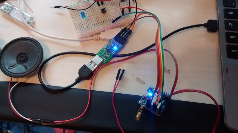
- Vcc straight to 5V (only if you have opened S1 to use the onboard diode as described above)
- GND to GND
- TX to RX
- RX to TX
- SPK to speaker
- SPKN to speaker
- FM to 1m wire as antenna
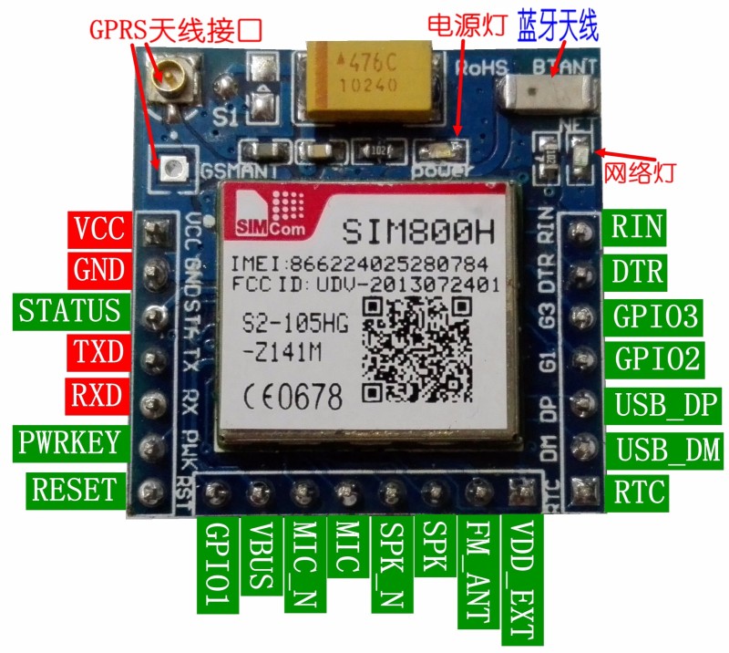
The picture with USB-Serial converter above was taken before i found out about the S1 connection, so i am using a diode on the breadboard to bring the USB voltage down – not needed if you open S1. The pinout diagram above was taken from Taobao and shows the module with S1 shorted and without the diode mounted, so this module would only be suitable for 4V. My units had the diode mounted, i only had to open S1.
Now you are ready to open your Serial Monitor in the Arduino IDE and talk directly to the SIM800 module. It is best to also connect a long wire (at least 1 meter) to the FM pin, as an antenna.
Some commands to try (see details in the application note):
AT+FMOPEN=0 (0 to use the main audio: SPK)
AT+FMVOLUME=6 (range 0-6)
AT+FMFREQ=1068 (range 875-1080, 10x frequency in MHz)
AT+FMSCAN (returns strong frequencies after scan)
AT+FMFREQ=881 (plays frequency 88.1 MHz)
AT+FMSIGNAL=881 (returns the signal strength at that frequency, but dips the audio)
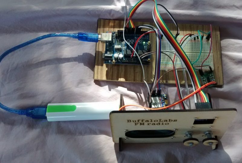
After this works, you’re ready to build a digital radio adding an Arduino as microcontroller to set the frequencies etc. I kept it simple with and OLED screen and just 2 potentiometers, to set the volume, and to set the frequency.

The 8ohm 3W speaker is plugged directly into the SIM800 module, and Arduino uses a Software Serial to send commands. I did not use the signal strength function because every time you call it, the audio drops a short period. I am living in a small village with no radio masts but i was able to catch a few stations but i had to play a lot with the antenna position, it seems extremely sensitive. I concatenated a few jumper wires to reach about 1m in length, straight on the FM antenna pin of the SIM800 module. Below a simple sketch of my hardware connections.

Below a video, with the sound of my radio!
Then i made laser cut panel for the OLED, speaker, and 2 potentiometers, and added a small class D 2x3W stereo amplifier, only using the Left channel. It’s powered by the same 5V, and only needs the SPKP as input (do not connect SPKN to the GND input on the amp); it works even without a blocking capacitor.


And here is the code:
^^^^^^^^^^^^^^^^^^^^^^^^^^^^^^^^^^^^^^^^^^^^^^^^^^^^^^^^^^^^^^^^^^^^^^^^^^^^^^^^^^^^
/*
SIM800L gsm module with Arduino UNO on 5V usb
Jan 2015 tomtobback@gmail.com www.cassiopeia.hk
SIM800 pins are supposed to be 5V tolerant, but power supply range is 3.4 to 4.4V: ideal for LiPo battery
my SIM800 breakout board has a DIODE to bring Vcc of 5V down to around 4.2V but need to REMOVE shortcut S1 (make it open to enable the diode)
add large capacitor e.g. 3300uF when using SIM card (not necessary for radio)
Vcc to 5V (make sure S1 is open)
GND to GND
TX to D5
RX to D6
RST to D7
OLED D13, D11, D8, D9, D10
SPK, SPKN to speaker
FM to antenna wire
potentiometer on A0 for VOLUME
potentiometer on A1 for FREQUENCY
*/
#include <SoftwareSerial.h>
SoftwareSerial sim800(5, 6);
#include “U8glib.h”
U8GLIB_SSD1306_128X64 u8g(10, 9); // OLED display: HW SPI CS = 10, A0/DC = 9 (Hardware Pins are SCK/D0 = 13 and MOSI/D1 = 11) + RST to Arduino D8
boolean SIMok = false;
int current_volume = 0;
int current_freq = 0;
//////////////////////////////////////////////////////////////////////////////////////////
//////////////////////////////////////////////////////////////////////////////////////////
void setup() {
pinMode(7, OUTPUT); // sim800 RESET pin
pinMode(8, OUTPUT); // RST pin for OLED display
digitalWrite(8, LOW);
delay(100);
digitalWrite(8, HIGH);
u8g.firstPage(); // intro splash
do {
u8g.setFont(u8g_font_fub14r);
u8g.drawStr(2, 30, “FM Radio”);
u8g.drawStr(2, 55, “BuffaloLabs”);
} while( u8g.nextPage() );
Serial.begin(9600);
sim800.begin(9600);
Serial.print(F(“Reset sim800 module.. “));
SIMok = false;
for (int i = 0; i < 3; i++) {
if (simReady()) {
SIMok = true;
break;
}
}
if (!SIMok) {}; // stop here if no SIM800 detected
sim800.println(“AT+FMOPEN=0”); // start FM radio on device 0 = main audio (SPK)
delay(1000);
simReply();
// Serial.println(“Scan for FM stations..”);
// scanFM();
// delay(10000);
// simReply();
}
//////////////////////////////////////////////////////////////////////////////////////////
//////////////////////////////////////////////////////////////////////////////////////////
void loop() {
int volume_pot = analogRead(A0);
int freq_pot = analogRead(A1);
int volume = map(volume_pot, 0, 900, 0, 6); // to make sure level 6 can be reached
int freq = 2 * map(freq_pot, 0, 1020, 436, 540); // 875 to 1080 in steps of 2
if (current_volume != volume) {
current_volume = volume;
setVolume(current_volume);
}
if (current_freq != freq) {
current_freq = freq;
setFreq(current_freq);
}
u8g.firstPage(); // intro splash
do {
u8g.setFont(u8g_font_fub14r);
u8g.setPrintPos(2, 30);
u8g.print(freq / 10.0, 1);
u8g.print(” MHz”);
u8g.setPrintPos(2, 50);
u8g.print(“volume: “);
u8g.print(volume);
} while( u8g.nextPage() );
}
//////////////////////////////////////////////////////////////////////////////////////////
//////////////////////////////////////////////////////////////////////////////////////////
//////////////////////////////////////////////////////////////////////////////////////////
boolean simReady() { // SIM READY
digitalWrite(7, LOW); // hardware reset after sleep RST
delay(1000);
digitalWrite(7, HIGH);
delay(3000);
sim800.println(“AT”);
delay(100);
// simReply();
if (sim800.find(“OK”)) {
Serial.println(F(“module OK”));
return true;
}
else
{
Serial.println(F(“sim800 module not OK, please check”));
return false;
}
}
//////////////////////////////////////////////////////////////////////////////////////////
void simReply() { // SIM REPLY
delay(100);
while (sim800.available()) {
Serial.write(sim800.read());
// char c = sim800.read();
// if (c != ‘\n’) Serial.write(c); // replace new line with space
// else Serial.print(” “);
// delay(5);
}
Serial.println();
}
///////////////////////////////////////////////////////////////////////////////////////////
void setVolume(int v) {
sim800.print(“AT+FMVOLUME=”);
sim800.println(v);
simReply();
}
///////////////////////////////////////////////////////////////////////////////////////////
void setFreq(int f) {
sim800.print(“AT+FMFREQ=”);
sim800.println(f);
simReply();
// sim800.print(“AT+FMSIGNAL=”);
// sim800.println(f);
// simReply();
}
///////////////////////////////////////////////////////////////////////////////////////////
void scanFM() {
sim800.println(“AT+FMSCAN”); // look for frequencies
/* for (int i = 0; i < 5; i++) {
delay(2000);
while (sim800.available()) {
int tmp = sim800.parseInt();
Serial.println(tmp);
}
} */
}
Pingback:Arduino kids phone (with SIM800) | Cassiopeia Ltd
Nice work; just what I was looking for 😉 (I’m using a picaxe instead of Arduino but some info above, cheers)
Stan
Hello,
nice work! It would be great to build in the bluetooth functionality, too.
So you can stream audio from smartphone to the speakers.
I am trying the same thing at the moment, but i have trouble connecting to my smartphone in A2DP profile.
“AT+BTGETPREF=1” don´t list “A2DP” profile for my smartphone, but i know, that it is supported!
Can you please try it with your SIM800H?
Thank you!
Regards Danie
Excellent work!
Could you please indicate where you got the SIM800 module. Does it have a particular part number?
This one has more pins than the HiLetgo module and I would like to explore other possibilities.
You also gave a good tip concerning the S1 switch, unfortunately not present on the HiLetgo module I purchased.
Again, congratulations and thanks for sharing.
Hi, i got it from Taobao.com as the link in my original post ‘arduino kids phone’ but the link seems indeed no longer available, so i’m not sure where we can get it now, sorry.
Where did You buy this board ?? I cannot find it anywhere :/
i bought it from taobao here https://world.taobao.com/item/522821256800.htm?spm=a312a.7700714.0.0.pwGX70#detail