This project again illustrates how to move from a (temporary) prototype using an Arduino board and breadboard towards a more permanent soldered (low cost) solution using the ATmega328 chip.
The idea is to use a cheap wall wart to deliver a DC voltage adjustable by turning a potentiometer while the voltage and current are displayed on an LCD.

![]()
![]()
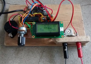
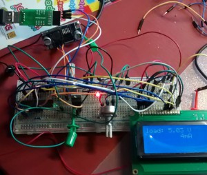
Left: prototype with Arduino Leonardo (‘Clio’), Middle: breadboard with ATmega328, Right: soldered setup
I started with an old power supply (wall wart) of 12V DC, connected to an adjustable DC/DC power converter. This converter has a 10K trim pot to adjust the voltage with a screwdriver. I un-soldered this trim pot and used a more convenient regular potentiometer as in the upper left of the picture.
The LCD uses the simple LiquidCrystal library with 4 data pins. I started with an 20×4 LCD which i still had lying around. The first picture shows my Seeeduino Clio board (Leonardo compatible).
SHUNT RESISTOR
I wanted to display the output voltage on an LCD, and the output current. Measuring the voltage is done with a simple voltage divider that feeds into an analog pin on the Arduino. The easiest way to measure the current is using a shunt resistor and i chose to put it on the high side in order to have a shared GND between the power supply, Arduino, and the power output (see disadvantage below). The current is calculated from the voltage measured over the shunt resistor, via another analog pin on the Arduino.
Then i replaced the Arduino board with an ATmega328P-PU on the breadboard. I burnt the bootloader and uploaded the sketch as i described in my previous post. I added a standard 7805 voltage regulator to bring down the 12V of the power supply (wall wart) to 5V for the ATmega and the LCD. I could have used this stable 5V as reference for the analog readings, but i chose to use the 1.1V internal analog reference of the ATmega328. The voltage divider resistors are both 100K/10K to bring down the max voltage of 12V to the max of the 1.1V analog reference (Aref).

RESOLUTION vs VOLTAGE DROP
I aim to measure currents up to 500mA. If i use a shunt resistor of 2 ohm, a current of 500mA will create a voltage of 1V over the shunt resistor. If i would use 10 ohm, the maximum voltage drop would be 5V which seems not very practical, but the resolution is a lot better:
- with analog reference set to 1.1V, the resolution (0-1023) is 1mV at the ATmega analog pins
- that means a 11mV resolution at the top of the voltage divider (would be same if we used 5V as Aref)
- with a shunt resistor of 2 ohm, that 11mV means a resolution of 5mA (Ohm’s law I=V/R) (POOR)
- with a shunt resistor of 10 ohm, that 11mV means a resolution of about 1mA (GOOD)
- the mA resolution is 11mV/R (11mV being the resolution if we want to measure a voltage up to 11-12V in 1023 steps)
So there is an important trade-off between a low voltage drop over the shunt resistor, and the current resolution. This seems to be the major disadvantage of having the shunt resistor at the high side, which allows us to share the GND between the power supply and output. It reduces the resolution because 2 relatively high voltages have to be measured (the problem is the same if we use 5V as analog reference). If we would put the shunt resistor on the low side, we could use a 1 ohm resistor, which at 500mA would give a reasonable voltage drop of 0.5V, with a resolution of 1mV=1mA if we use Aref of 1.1V. But then the GND is not shared, which seems an important disadvantage. TI has an interesting tutorial on current measurement, low and high side shunt, they suggest a special opamp to amplify the voltage difference over the shunt to a (low) voltage (vs GND) to be measured e.g. by the Arduino. In our solution we won’t use such opamp.
A high voltage drop would be a problem when we would have variations in the current, i.e. a motor of 5V with a max current of 500mA. We would set the voltage at 5V with 0mA, but when the motor starts drawing 500mA, the voltage over the 10 ohm shunt resistor would increase to 5V, leaving 0V for the motor, which wouldn’t work of course; we’d have to manually ramp up the DC converter’s output voltage to 10V to keep 5V at the motor, but when the motor stops it would suddenly get 10V. The solution could be to use a digital potentiometer which would change the DC output voltage to keep the voltage over the load (e.g. motor) constant at the required level.
I added a piezo buzzer to pin 9 which gives off an alarm when the calculated current goes over 300mA which in my low power installations would usually indicate there is a short circuit somewhere. As i like to do, i screwed the different parts on a piece of wood as below.

Pingback:INDUSTRUINO digital power supply | Cassiopeia Ltd