This is an Arduino-based battery powered air quality monitor using the optical SHARP GP2Y1010AU0F dust sensor (or its more recent version the GP2Y1014). It reports values in micrograms per cubic meter, which is also the unit of PM2.5 and PM10.
Having lived in Beijing for many years, i am quite concerned about air pollution, even in Hong Kong where luckily the situation is a lot better. After experimenting a bit with dust sensors that are supposed to correlate with PM2.5 and PM10, i decided to build a portable sensor. For my first prototype i used an Industruino PROTO 32u4 kit, without its usual DIN-rail casing; i put it in a laser cut wooden box. A second version uses a cheap 16×2 LCD and a ‘bare-bones’ Arduino on a PCB (see below).

For reasons outlined here, i opted for the SHARP GP2Y1010AU0F dust sensor (optical), which outputs a voltage that correlates with the volumetric unit of standard PM measurements. However, the datasheet and this application note do not mention the upper diameter of the dust measured (e.g. 2.5 or 10 micron) so we do not know if it is intended to measure PM2.5 or rather PM10. So i have chosen to just call it the ‘dust concentration’ to be clear about this.
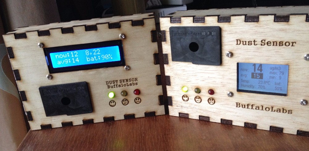
The LCD shows the current measurement, refreshed every 2 seconds, as an average of 200 samples, with pulse interval of 10 milliseconds as in the application note. It also shows the long-term average since the unit was switched on, and the minimum and maximum values since the unit was switched on.
PROTOTYPE
The Industruino PROTO kit consists of a topboard PCB with the MCU (32u4 = Arduino Leonardo) and an LCD, and a baseboard with a prototyping area for soldering. I decided to also include a DHT22 temperature/humidity sensor, with pull-up resistor. I added the 150 ohm resistor and 220uF capacitor necessary for the SHARP sensor. And 3 LEDs to indicate 3 levels (green, yellow, red).
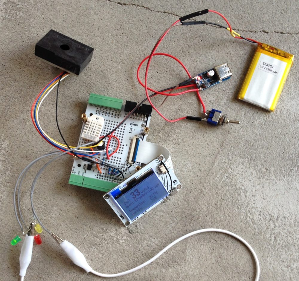
I am powering this project from a LiPo 1200mAh battery cell, with a switch, and a USB booster that brings the voltage up to 5V (necessary to get the full scale of the SHARP sensor).
The code is fairly straight forward, i did make an effort to follow the recommendations of the SHARP datasheet in detail regarding pulse length and interval, because using a different interval seems to affect the results (higher readings). I’m taking the average of 100 samples, so the screen refreshes every 1 second.
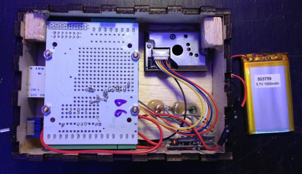
Everything fits nicely together in the box, i attached the top and base PCBs to the front panel and applied hot glue to put the panels together.
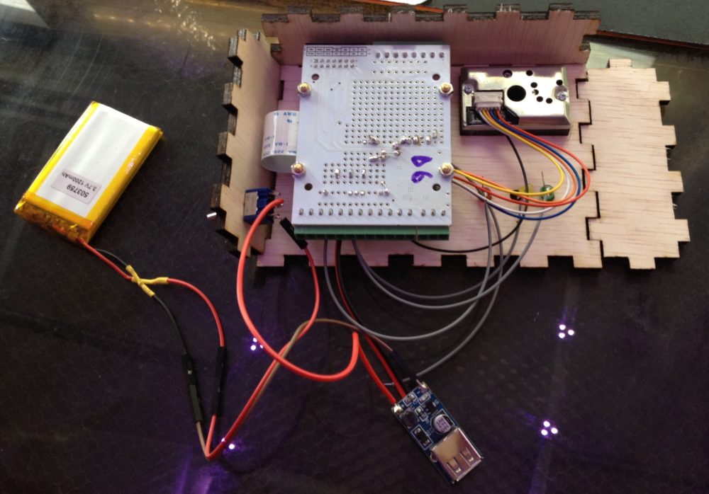

The battery is stuck to the back panel.
SECOND VERSION
Made out of readily available components, with an Atmega328P on a soldered perf board, and the 16×2 LCD plugged into that with a row of 16 male/female headers.


I bought the sensor from Taobao and although it is sold as a GP2Y1010AU0F type, they sent me the GP2Y1014 type, which is NOT the same. I could not find any reliable datasheet for this type, but using the same 10 millisecond sampling interval gave me zero values. Only when i included a delay(100) between the samples it returned realistic values, similar to the GP2Y1010. So instead of displaying the average of 200 sample, i am using only 20 samples with this sensor.

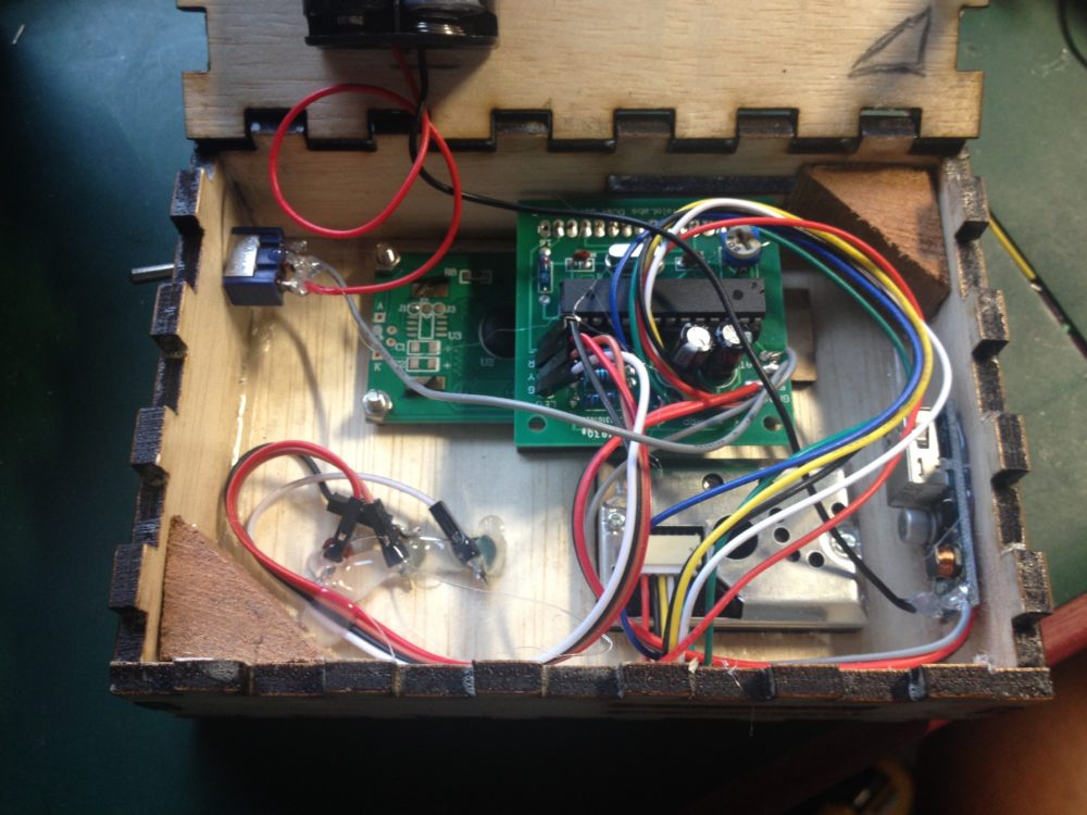
The layout inside the box, with DC/DC booster on the left, to bring the 3V battery output to 5V.
The 2 versions seem to report similar values, more testing and benchmarking with professional sensors needed.
PCB VERSION

Code for the 16×2 LCD version:
/*
 Arduino barebones 16MHz (duemilenova) with SHARP dust sensor
 SHARP GP2Y1010AU0F dust sensor output on A0
 timings according to datasheet https://www.sparkfun.com/datasheets/Sensors/gp2y1010au_e.pdf

2xAA bat with USB booster and large cap 1500uF on 5V, GND
 battery voltage on A5

LCD 16x2
 * LCD RS pin to digital pin 7
 * LCD Enable to digital pin 6
 * LCD D4 pin to digital pin 5
 * LCD D5 pin to digital pin 4
 * LCD D6 pin to digital pin 3
 * LCD D7 pin to digital pin 2
 * LCD R/W pin to ground
 * LCD VSS pin to ground
 * LCD VCC pin to 5V
 * 5K pot to LCD VO pin

 AREF to 5V (seems necessary; without this, AREF gave around 4.2V)
 BuffaloLabs 2017, Tom Tobback
*/

// include the library code:
#include <LiquidCrystal.h>

// initialize the library with the numbers of the interface pins
LiquidCrystal lcd(7, 6, 5, 4, 3, 2);

const int SHARP_LED_PIN = 8; // inverted
const int LED_GREEN_PIN = 9;
const int LED_YELLOW_PIN = 10;
const int LED_RED_PIN = 11;

// SHARP SENSOR VARIABLES
const int samples = 4; // with delay of 10ms in between as per datasheet /// more needed for GP2Y1014!!
const int upper_limit_green = 20;
const int upper_limit_yellow = 50;

unsigned long concCum = 0; // to calculate all-time average concSHARP for displaying
unsigned long counter = 0; // counter for all-time average

int concMax = 0; // to keep track of min and max
int concMin = 500;

void setup(void) {

pinMode(SHARP_LED_PIN, OUTPUT); // SHARP LED switch
 pinMode(SHARP_LED_PIN, HIGH); // LED off

 pinMode(LED_GREEN_PIN, OUTPUT);
 digitalWrite(LED_GREEN_PIN, HIGH);
 pinMode(LED_YELLOW_PIN, OUTPUT);
 digitalWrite(LED_YELLOW_PIN, HIGH);
 pinMode(LED_RED_PIN, OUTPUT);
 digitalWrite(LED_RED_PIN, HIGH);

Serial.begin(9600);
 Serial.print("SHARP dust sensor GP2Y1010/1014 with sample number: ");
 Serial.println(samples);

lcd.begin(16, 2);
 lcd.setCursor(0, 0);
 lcd.print("BuffaloLabs");
 lcd.setCursor(0, 1);
 lcd.print("DUST SENSOR v1.0");

digitalWrite(LED_GREEN_PIN, LOW);
 digitalWrite(LED_YELLOW_PIN, LOW);
 digitalWrite(LED_RED_PIN, LOW);

delay(100);
}

/////////////////////////////////////////////////////////////////////////////////////
/////////////////////////////////////////////////////////////////////////////////////

void loop(void) {

//////////////////////////////////////////// READ SHARP SENSOR ////////////////////////////////////////////////
 float dust_voltage = 0;
 int dust_analog;
 for (int i = 0; i < samples; i++) {
 digitalWrite(SHARP_LED_PIN, LOW); // power on the LED
 delayMicroseconds(280); // DATASHEET pulse width 0.32ms = 280us + 40us
 dust_analog = analogRead(A0); // read the dust value
 delayMicroseconds(40); // DATASHEET pulse width 0.32ms = 280us + 40us
 digitalWrite(SHARP_LED_PIN, HIGH); // turn the LED off
 delayMicroseconds(9680); // DATASHEET recommended pulse cycle 10ms = 320us + 9680us
 dust_voltage += dust_analog * 5.0 / 1023.0 ; // voltage 0-5V
 delay(500); // only for GP2Y1014!!! remove for GP2Y1010 and increase sample size to 200
 }
 dust_voltage = dust_voltage / samples;

// CALCULATE SHARP RESULTS
 int concSHARP = 172 * dust_voltage - 100; // density microgram/m3
 concSHARP = constrain(concSHARP, 0, 500);

 concCum += concSHARP; // for all-time average
 counter++;
 int concAvg = concCum / counter;

 if (concSHARP > concMax) concMax = concSHARP; // update min and max
 if (concSHARP < concMin) concMin = concSHARP;

//////////////////////////////////////// READ BATTERY VOLTAGE ///////////////////////////
 int battery_analog = 0; // take average of 5 battery voltage readings to reduce noise
 for (int i = 0; i < 5; i++) {
 battery_analog += analogRead(A5);
 delay(10);
 }
 battery_analog = battery_analog / 5;
 long battery_voltage = 10L * 5L * battery_analog / 1023L; // times 10 for integer value (larger than int, use long)
 int battery_percent = map(battery_voltage, 20, 30, 0, 10); // divided by 10 for less noise, only in 10s
 battery_percent = constrain(10 * battery_percent, 0, 100);

/////////////////////////////////////// PRINT DATA TO SERIAL ////////////////////////////////
 Serial.print(dust_voltage);
 Serial.print("\t\t");
 Serial.print(concSHARP);
 Serial.print("\t\t");
 Serial.print(concCum);
 Serial.print("\t\t");
 Serial.print(counter);
 Serial.print("\t\t");
 Serial.print(concAvg);
 Serial.print("\t\t");
 Serial.print(battery_voltage);
 Serial.print("\t\t");
 Serial.println(battery_percent);

////////////////////////////////////////////// DISPLAY ///////////////////////////////////////

 if (counter == 1) lcd.clear();
 lcd.setCursor(0,0);
 lcd.print("now:");
 lcd.print(concSHARP);
 lcd.print(" ");
 lcd.setCursor(0,1);
 lcd.print("avg:");
 lcd.print(concAvg);
 lcd.print(" ");
 lcd.setCursor(8,0);
 lcd.print(concMin);
 lcd.print(",");
 lcd.print(concMax);
 lcd.print(" ");
 lcd.setCursor(8,1);
 lcd.print("bat:");
 lcd.print(battery_percent);
 lcd.print("% ");

/////////////////////////////////////////////// SWITCH LED INDICATORS /////////////////////////////////////
 if (concSHARP < upper_limit_green) { // based on short time average
 digitalWrite(LED_GREEN_PIN, HIGH);
 digitalWrite(LED_YELLOW_PIN, LOW);
 digitalWrite(LED_RED_PIN, LOW);
 }
 else if (concSHARP < upper_limit_yellow) {
 digitalWrite(LED_GREEN_PIN, LOW);
 digitalWrite(LED_YELLOW_PIN, HIGH);
 digitalWrite(LED_RED_PIN, LOW);
 }
 else {
 digitalWrite(LED_GREEN_PIN, LOW);
 digitalWrite(LED_YELLOW_PIN, LOW);
 digitalWrite(LED_RED_PIN, HIGH);
 }

}

//////////////////////////////////////////////////////////////////////////////////////////////////////////////
Hi Tom,
I just love that laser cut box that you’ve made.
Like most Arduino sketches that I’ve seen for the Sharp sensor you’re using analogRead(). This takes too long to give you the pulse width that the sensor is calibrated to. The problem is that the ADC takes longer to complete the conversion than the time between taking the measurement and turning off the LED. Have a look at my blog (connectranet.co.uk) for some oscilloscope traces and code using an ISR to get the correct pulse width.
Hi Andy, thanks a lot for the feedback. Yes i have been worried about that timing, i’ll have a good look at your solution.
Can i ask a question?
i can’t understand this line
int concSHARP = 172 * dust_voltage – 100;
gp2y1010 data sheet say
this sensor’s sensitivity is 0.5V per 0.1mg/m3
then
‘ consSHARP = (dust_voltage – no dust value) * 0.005 ‘ isn’t it?? –(want to make ug/m3)
i want to know why you use ‘ concSHARP = 172 * dust_voltage – 100; ‘ this code
please look at Fig3 in the datasheet, it shows the relation between voltage and density, fitting a line to this curve gives this equation
Pingback:Upgrading dust sensor to laser (PMSA003) – Cassiopeia Ltd