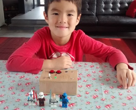
When my 5 year old son asked me for a phone, i told him i would make one for him.
The phone uses an Arduino and a SIM800L module that i bought on Taobao for RMB 35. There are a lot of variations, i chose this one because it has connections for speaker and microphone, and works directly with the 3.7V of a LiPo battery. Other versions have less pins (basically only RX/TX) or a lot more components but this one is perfect for my project.

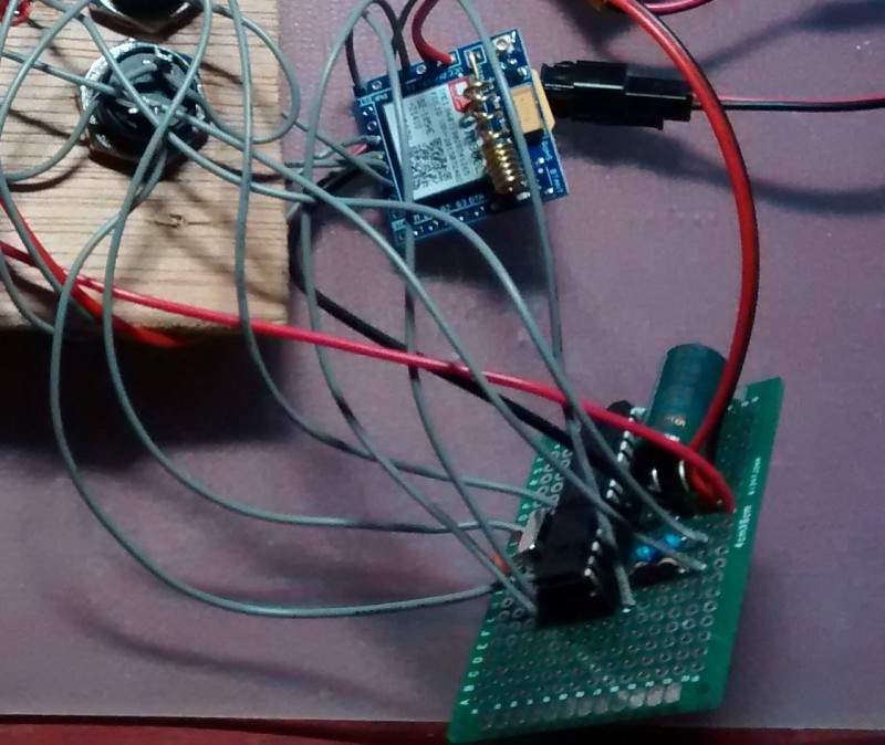
I soldered the pin headers to the SIM800 module and made a prototype with Arduino board (red Seeeduino below), a breadboard with 3 buttons and a electret microphone, and a 8ohm speaker. The speaker and microphone connect directly to the SIM800 module.

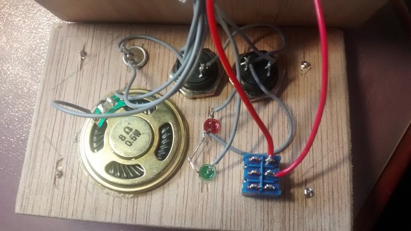
Initially i used 3 buttons: call mum, call dad, answer/hang up call; but in the final version i figured that the 3rd button is not needed, we can answer/hang up with any of the other 2 buttons. I added a green LED for the status of the phone: after power on, it blinks while the SIM card is being registered on the network, and then stays on to indicate the phone is ready to make/receive calls. The red LED blinks when there is an incoming call, and stays on during the call. [i tried several SIM cards in Hong Kong: CSL works, for some reason 3HK and Smartone do not seem to work]
The communication between SIM800 and Arduino goes over a Software Serial, and uses standard AT commands, with an excellent datasheet (multiple versions available online). The hardware datasheet does not mention it, but this thread on the Arduino forum claims the RX/TX pins are 5V tolerant. I did not take any chances and put my Seeeduino in 3.3V mode. My aim was to power the Arduino (and the SIM800) from a 3.7V LiPo battery so i was only using 5V while the Arduino was connected to my laptop for uploading sketches and debugging over the Serial Monitor. Even then i needed to have the LiPo battery connected to the SIM800 module because it can draw a lot more current than the laptop USB can provide. I also added a large capacitor of 1500uF to stabilise the voltage. It is possible to use this module with 5V if you activate the onboard diode, as i describe in this other post.
I did not want to use my Arduino board inside the phone, so i made a barebones Arduino (ATmega328P at 16MHz, see my other post) and soldered the few components on a perf board (2x 22pF caps, the 16MHz crystal, the 1500uF cap, 2 resistors for LEDs, and the wires going to the switch, buttons and LEDs.
In my sketch i’m not using a SIM library for the AT commands, but rather writing them directly over the Software Serial and decoding the reply, to know exactly what is going on in the SIM800 module. [see my sketch in comments below]
As soon as my prototype was working, i started to make a wooden box, out of 5mm board. The corner pieces are screwed to the base board and the side panels are glued together.
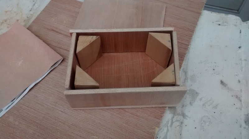
I sanded the edges, drilled holes in the front panel, and put a varnish on it.

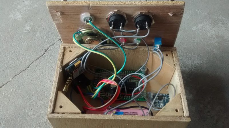
I fixed the perf board with the ATmega328 to the base board, and let the SIM800 float around as there are no holes in this PCB to fix it.

I attached all the components to the front panel as below, using glue for the speaker.
And the end result looks quite OK i think, and more importantly, it works!

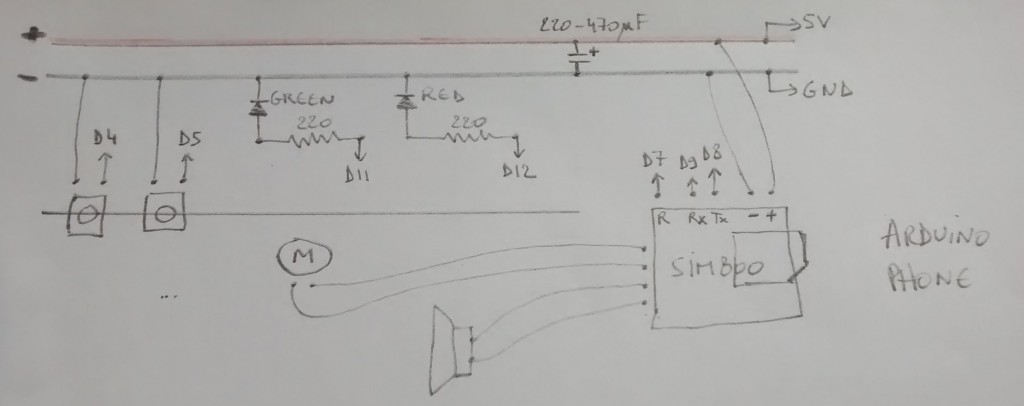
For a breadboard version of this phone, see below drawing that works with the sketch below, and runs on 5V (see this post on how to use this module with 5V).

And a second version of the same project, with a recycled laptop battery cell and DC-DC booster to bring that up to 4.2V; the SIM800 module from a new batch seems to easily loose the network connection under 4V.

Isn’t the speaker too quiet? My 0,5W 8 ohm speaker connected to SIM800L core board is barely audible. The same with mic, almost no input. Is there a simple way to turn volume up a little? Nice cellphone by the way 🙂
Hi Marcin, thanks for your message. My speaker’s also 8ohm 0.5W and i get a decent volume. You can set the volume with the following AT command:
sim800.println(“AT+CLVL=80”); // set speaker volume 0-100
Actually, let me post my entire sketch here, you can find some other AT commands at the end to set the ringer volume, ring tone, and microphone gain. I do get quite a lot of noise on the mic, heard on the other phone, but when speaking into the SIM800 mic the noise is not a problem.
/*
SIM800L gsm module on LiPo battery
Dec 2015
do not connect to 5V logic, use 3.3V option or power Arduino from LiPo
GND
TX to D8
RX to D9
RST to D7
LED on D11 green = system status:: on=ready blinking=starting
LED on D12 red = call status:: on=in call blinking=ringing
button on D4 : call number 1 and answer/hang up
button on D5 : call number 2 and answer/hang up
*/
#include
SoftwareSerial sim800(8,9);
char phone_number1[]=”+xxxxxx”; // put phone number here, international format, no spaces
char phone_number2[]=”+xxxxxx”;
unsigned long time_pressed4;
unsigned long time_pressed5;
boolean SIMok = false;
int current_status;
void setup() {
delay(5000);
pinMode(4, INPUT_PULLUP);
pinMode(5, INPUT_PULLUP);
pinMode(11, OUTPUT); // green LED
pinMode(12, OUTPUT); // red LED
digitalWrite(11, HIGH); // blink green and red LED
digitalWrite(12, HIGH);
delay(500);
digitalWrite(11, LOW);
digitalWrite(12, LOW);
pinMode(7, OUTPUT); // sim800 RESET
digitalWrite(7, LOW);
Serial.begin(9600);
sim800.begin(9600);
Serial.print(F(“Testing sim800 module.. “));
SIMok = false;
for (int i=0;i<3;i++) {
if (simReady()) {
SIMok = true;
break;
}
}
if (SIMok) simDetails(); // get some details on SIM
else { // if SIM not OK then blink RED forever
for (;;) {
digitalWrite(12, HIGH);
delay(100);
digitalWrite(12, LOW);
delay(100);
}
}
digitalWrite(11, HIGH); // green LED on for SIM ok
}
void loop() {
current_status = checkStatus();
// Serial.println(current_status); // 48: ready 51: ringing 52: in call
if (current_status == 52) { // IN CALL (should be 4 according to datasheet)
Serial.println("52: in call");
digitalWrite(12, HIGH); // red LED on when in call
delay(500);
if (!digitalRead(4) || !digitalRead(5)) { // if push any button hang up call
digitalWrite(12, LOW); // red LED off after hang up
sim800.println("ATH");
Serial.println(F("Hanging up call"));
simReply();
}
}
else {
if (current_status == 51) { // RINGING (should be 3 according to datasheet)
Serial.println(F("51: incoming call.."));
digitalWrite(12, HIGH); // blink red LED when ringing
delay(500);
digitalWrite(12, LOW);
if (!digitalRead(4)|| !digitalRead(5)) { // if push any button answer call
digitalWrite(12, HIGH); // red LED on when in call
sim800.println("ATA");
Serial.println(F("Answering call"));
simReply();
}
}
else {
digitalWrite(12, LOW);
if (digitalRead(4)) time_pressed4 = millis(); // button not pushed
else if (millis() - time_pressed4 > 500) simCall(phone_number1); // button pushed, call if long push
if (digitalRead(5)) time_pressed5 = millis(); // button not pushed
else if (millis() – time_pressed5 > 500) simCall(phone_number2); // button pushed, call if long push
}
}
}
boolean simReady() { // SIM READY
digitalWrite(7, LOW); // hardware reset after sleep RST
delay(1000);
digitalWrite(7, HIGH);
// time to startup 3 sec
for (int i=0;i<6;i++) {
digitalWrite(11, HIGH); // green LED blink
delay(250);
digitalWrite(11, LOW);
delay(250);
}
sim800.println("AT");
delay(100);
if (sim800.find("OK")) {
Serial.println(F("OK"));
Serial.print(F("Registering on the network.."));
for (int i = 0; i<20; i++) {
// time to register on network 2.5 sec
for (int i=0;i<5;i++) {
digitalWrite(11, HIGH); // green LED blink
delay(250);
digitalWrite(11, LOW);
delay(250);
}
Serial.print(".");
sim800.println("AT+CREG?"); // possible replies: 0,0=not registered 0,1=registered on home network 0,2=not registered but searching 0,3=denied 0,4=unknown 0,5=roaming
delay(1000);
if (sim800.find("0,1")) {
Serial.println(F(" OK"));
return true;
}
}
Serial.println(F("failed to register for 1min, will reset sim800"));
return false;
}
else
{
Serial.println(F("sim800 module not OK, please check"));
return false;
}
}
void simReply() { // SIM REPLY
delay(500);
while (sim800.available()) {
char c = sim800.read();
// if (c != '\n') Serial.write(c); // replace new line with space
// else Serial.print(" ");
delay(5);
}
// Serial.println();
}
int checkStatus() { // CHECK STATUS FOR RINGING or IN CALL
sim800.println("AT+CPAS"); // phone activity status: 0= ready, 2= unknown, 3= ringing, 4= in call
delay(500);
if (sim800.find("+CPAS: ")) { // decode reply
char c = sim800.read();
simReply();
return c;
}
else return -1;
}
void simCall(char number[]) {
digitalWrite(12, HIGH);
Serial.print("Start call.. ");
sim800.println("AT+CREG?"); // possible replies: 0,0=not registered 0,1=registered on home network 0,2=not registered but searching 0,3=denied 0,4=unknown 0,5=roaming
delay(1000);
if (sim800.find("0,1")) {
Serial.println(F("network connection still OK"));
simReply();
}
else {
SIMok = false;
for (int i=0;i<3;i++) {
if (simReady()) {
SIMok = true;
break;
}
}
if (!SIMok) { // SIM not ok, blink RED forever
for (;;) {
digitalWrite(12, HIGH);
delay(100);
digitalWrite(12, LOW);
delay(100);
}
}
}
Serial.print("Calling number ");
Serial.println(number);
String cmd; // make call command
cmd = "ATD";
cmd += number;
cmd += ";";
sim800.println(cmd);
delay(1000);
simReply();
}
void simDetails() {
Serial.print(F("operator:"));
sim800.println("AT+COPS?"); // OPERATOR
delay(500);
if (sim800.find(":")) { // decode reply
while (sim800.available()) {
char c = sim800.read();
if (c != '\n') Serial.write(c); // replace new line with space
else Serial.print(" ");
delay(5);
}
}
else Serial.print(F("n/a"));
Serial.println();
Serial.print(F("signal strength:"));
sim800.println("AT+CSQ"); // SIGNAL STRENGTH
delay(500);
if (sim800.find(":")) { // decode reply
while (sim800.available()) {
char c = sim800.read();
if (c != '\n') Serial.write(c); // replace new line with space
else Serial.print(" ");
}
}
else Serial.print(F("n/a"));
Serial.println();
Serial.print(F("battery level:"));
sim800.println("AT+CBC"); // BATTERY LEVEL
delay(500);
if (sim800.find(":")) { // decode reply
while (sim800.available()) {
char c = sim800.read();
if (c != '\n') Serial.write(c); // replace new line with space
else Serial.print(" ");
}
}
else Serial.print(F("n/a"));
Serial.println();
sim800.println("AT+CLVL=80"); // set speaker volume 0-100
simReply();
sim800.println("AT+CRSL=80"); // set ringer volume 0-100
simReply();
sim800.println("AT+CMIC=0,12"); // set mic to gain level 0-15
simReply();
// ring tone AT+CALS=5,1 to switch on tone 5, 5,0 to switch off
sim800.println("AT+CALS=19"); // set alert/ring tone
simReply();
Serial.println("Ready");
}
Thank you, it seems I just have missed it reading sim800 command manual 🙂
I think as well that the scoreboard exposes only spk1 pins. According to the datasheet these pins are good for directly driving a 32Ohm speaker. Spk2 pins are good for driving an 8Ohm speaker.
I find that connecting an 8ohm speaker to spk1 causes the module to shut down after issuing either under or over voltage warnings. Too much current sourced from the pins. So far I have fried two modules with this.
Not scoreboard but core board. Damn auto autocorrect….
Hi Justin, i have not had any problems of that kind; i have been using 8ohm speakers (0.5W) of different kinds without any shutdowns. Maybe we’re using different breakout boards. I’ve also used it as FM radio continuously for hours, e.g. with a 8ohm 2W speaker without any problem (see other post).
don’t use delay in incomming data from sim800, response time max is 300 ms and you are using delay every time you need to listen module
Pingback:Arduino FM radio (with SIM800) | Cassiopeia Ltd
Pingback:Remote control by Arduino phone DTMF (with SIM800) | Cassiopeia Ltd
Hi!
I’m using the sim800l module with an arduino and a electret microphone, and i can’t configure the mic to hear the voice of another person when i make a call.
What commands do you enter in order to configure it? (i was reading the datasheet and i found AT+CEXTERNTONE=1 to open the mic, AT+CMIC=0,12 to change the level of gain and AT+CMICBIAS=1 to open de bias, the last i believe that is only for record. Am i right?)
Thanks!
Hi Alexis, the electret mic is only for input; you will need a speaker to hear the other person’s voice
Yes, of course. I’m doing an university’s project and i want only to hear the other side when i call to the module. What commands did yo use? Did you connect the electret mic directly to the pins micp, micn form the sim800? I found a schematic on page 36 form a pdf but i don’t know if belongs to this the sim800L.
This is the pdf’s link: https://www.maritex.com.pl/media/uploads/PRODUKTY_PDF/wireless/Simcom/SIM800-Hardware-Design-V1.08.pdf
Thanks
Hi Alexis, yes i connected the electret mic straight to the pins MIC and MIC_N as labelled on my breakout board above, which i assume are connected directly to the SIM800 pins. my code is above, i only adjust the gain with sim800.println(“AT+CMIC=0,12”); // set mic to gain level 0-15
not the other 2 commands that you mentioned
Hi
Nice job! I am trying to connect my arduino uno to sim800l module. The problem I am facing is that the sim module stays on for a few hours and then disconnects and do not reconnect again.
I have used a 220 to 12 v dc adaptor(switching) and then a dc to dc switching convertor module to bring voltage to 4 volts for sim module. I used the same 12 volt adaptor to power arduino through its power jack.
What can be the reason of disconnecting?
Hi Moh, thanks for your feedback. I’m not sure what could cause your disconnection issue; i have not left my project switched on for such a long time. I would suggest you include a regular check in your sketch to see if the connection is still active, and if not, maybe reset the module automatically. Tom
I want to make two sets of this project..both can call each other by speaking and hearing at the same time..but without buttons to press…
How can I make two sets to communicate without button to press
Hi Nimir, thanks for the feedback. I think you will need at least 1 button on your phone project, to initialise the call. On the receiving end, you can modify the sketch to just accept the call as soon as it comes in, without pressing a button to accept the call. You could also modify the sketch to call the other side as soon as the module is switched on, without pressing a button. But that obviously would not work on both sides because one side needs to be listening before calling. So if you want the 2 sides to be able to initialise the call, you will need a button one each side. Good luck – Tom
thanks for sharing… 😀
Hello, it’s a very nice project, I want to ask you: does SIM800H support GPS? or it’s only GSM?
Thank you
Hi Khaled, SIM800 does not have GPS, you’ll have to get a SIM808 for that
Hi
I’m getting a lot of gsm noise on my sim800 and sim900 boards. I’ve tried premade sim900s and sim800 and also homemade versions of both. All the same – persistent gsm interference and worse during calls.
Tried powering with a lipo battery bank, from usb wall wart, from a 12v battery via a buck converter but it is always the same. Bad enough to make a call impossible. Have tried wrap around suppression beads too. No benefit.
Really not sure what to try next. Need to find a solution as this is for a gate that is too far from the house to get wired signals.
Do you suffer from any noise issues?
Thanks
Justin.
Hi Justin, yes i also had noise issues on one of the boxed versions i made; adding ferrite beads did not help me much either. The main issue seems noise getting into the mic, which seems very dependent on the position of the SIM800 board. With the project on a breadboard, and the SIM800 board at some distance (say 20cm) noise is minimal. I have 2 boxed versions of the project; one continues to have a lot of noise (mic generating noise for the other side), but my other box is much better, it seems to depend on the position of the SIM800 board so i’d suggest you experiment with that to minimise the noise, hope that helps.
I don’t know how far your gate is but maybe a walkie-talkie setup with the nRF24L01 could work? https://cassiopeia.hk/walkietalkie/ (you will need a more powerful antenna than i used in that project)
Hi, i tried compiling your code, but there where lots of error messages,
Arduino: 1.6.5 (Windows 8.1), Board: “Arduino Uno”
Build options changed, rebuilding all
Using library SoftwareSerial in folder: C:\Program Files\Arduino\hardware\arduino\avr\libraries\SoftwareSerial
C:\Program Files\Arduino\hardware\tools\avr/bin/avr-g++ -c -g -Os -w -fno-exceptions -ffunction-sections -fdata-sections -fno-threadsafe-statics -MMD -mmcu=atmega328p -DF_CPU=16000000L -DARDUINO=10605 -DARDUINO_AVR_UNO -DARDUINO_ARCH_AVR -IC:\Program Files\Arduino\hardware\arduino\avr\cores\arduino -IC:\Program Files\Arduino\hardware\arduino\avr\variants\standard -IC:\Program Files\Arduino\hardware\arduino\avr\libraries\SoftwareSerial C:\Users\admin\AppData\Local\Temp\build7916401781335559693.tmp\phone.cpp -o C:\Users\admin\AppData\Local\Temp\build7916401781335559693.tmp\phone.cpp.o
phone.ino:56:1: error: stray ‘\’ in program
phone.ino:56:1: error: stray ‘\’ in program
phone.ino:112:2: error: stray ‘\’ in program
In file included from C:\Program Files\Arduino\hardware\arduino\avr\cores\arduino/WString.h:29:0,
from C:\Program Files\Arduino\hardware\arduino\avr\cores\arduino/Print.h:26,
from C:\Program Files\Arduino\hardware\arduino\avr\cores\arduino/Stream.h:26,
from C:\Program Files\Arduino\hardware\arduino\avr\libraries\SoftwareSerial/SoftwareSerial.h:36,
from phone.ino:27:
phone.ino: In function ‘void setup()’:
phone.ino:56:17: error: ‘u201cTesting’ was not declared in this scope
phone.ino:56:14: note: in expansion of macro ‘F’
phone.ino:56:30: error: expected ‘)’ before ‘sim800’
phone.ino:56:14: note: in expansion of macro ‘F’
phone.ino: In function ‘void loop()’:
phone.ino:109:51: error: ‘phone_number1’ was not declared in this scope
phone.ino:112:21: error: expected ‘)’ before ‘u2013’
phone.ino:112:56: error: ‘phone_number2’ was not declared in this scope
stray ‘\’ in program
Hi Maxwell, thanks for your message. WordPress does a horrible job when i try to include code in my posts; it deletes stuff and uses some wrong chars.
at the top of the code there is a line #include that actually should read:
#include
and i suspect some of the lines were broken into 2, you can fix that by reading the code.
sometimes also the quote marks are changed into something arduino does not like.
the code is provided for reference, i know it does not work copy/paste.
Hi Tom,
thanks for posting, this is helping me with my thesis :). I have one question, which is the mAh of your LiPo battery?
Greetings from Venezuela.
hi Leo, 1600mAh
Hello Tom, do you think I can put jack to use a 3.5mm auxiliary cable to connect microphone-audio, audio-microphone, into a computer?
Hi, that’s an interesting question, not sure what you want to achieve. i’m guessing you want to use the mic/speakers of your computer to speak/listen? then you’d have to cross the connections (sim800 speaker = output => input = laptop’s mic, and sim800 mic = input <= laptop's audio out). it might work, but i guess you'd have to put the audio volume on your laptop extremely low (to reduce to the level of the electret mic), or put a resistor in between. not sure about this.
Please help!!
what are AT commands to play recorded audio file from storage (or any other way) on Voice call like auto answering machine
e.g. If we call to customer care we hear that “to do this press 1.. to do that press 2..”
Hi, i have not tried any of that. I see there is indeed a RECORD function, with AT+CREC, you can check the AT commands manual. You could also try the Text To Speech (TTS) feature of some of the SIM800 chips, e.g. the SIM800L, i don’t have one, so i have not tried.
Hi Tom
As. Newcomer to the world of Arduino, I’m making a mobile-phone-in-a-box for my four year old niece, who is about to move to the other end of the country. She can get the box out, switch it on and press the “Call Uncle Simon” button.
So I’m wondering about incorporating a loudspeaker rather than earplugs, and I google “SIM800L speaker” to find out what I might use. Top of the search results comes your project! What a delight to see that someone has beaten me to it! This is exactly what I’m in the process of making. I plan to include an RTC so that the calls will be restricted to reasonable times of day, maximum one a day, maximum 5 minutes per call, etc (keep the parents happy!)
There are endless possibilities – more buttons for more relatives, handling incoming calls, displaying a message on LCD when switched on, and so on.
We’ll see how it develops and grows over the years. Thank you for putting yours online, it looks just great!
Best wishes
Simon
Hi Simon, feel free to post a link to any description of your project, i’d be eager to have a look at it, good luck
Thanks Tom, I’ve started a new blog for my electronics projects, this is the first entry! https://electronicssimoninthelakes.wordpress.com/2018/09/08/amyphone-project/
Version 2.0 is in progress, and there are plans for a Version 3 with the four phone numbers on SD card, so that parents can change them.
Hi again Tom and anyone else following this adventure. My Version 3.0 is now live, with more solutions to more problems, and more thoughts for the future.
I’m happy to discuss any aspects of this project, either here or on my blog post.
https://electronicssimoninthelakes.wordpress.com/2018/11/12/amiphone-3-0/
looks great, well done!
Nice One. I’m trying the similar one with mic as input and speaker as output. But the microphone is generating much disturbance and can’t even receive the voice from another end. I’m using Electret Microphone for voice input .I donno where am going wrong. You can find the image of mic here https://ibb.co/igEdVp .. Is that mic works or I should go for another mic. Can you please help me out with this
hi, it seems your mic has an adjustable gain, while the one i’m using is a bare electret mic without any amplification. maybe yours will work if you manage to lower the gain to 1. or get a simple one without amplifier.
hello sir,
Thank you so much ….
Hi @Tom,
Are this project (module sim800L) still working on 2019 ? 😀
I’m affraid about 2G availability
well that depends on your location; here in Hong Kong we still have 2G available but i hear indeed other countries are phasing it out. replacing the SIM800 with a 3G or 4G module should not be very difficult as i think most modules use the same AT commands.
yeah it’s no doubt great project. and i’m coming up with question which is : even after registration of my gsm module, it’s not catching signal. do you have any idea what could be the case?
and do i have to use microphone directly or with any additional circuitry.
you will have to make sure the SIM card you are using supports 2G; in some countries the 2G network has been taken down already.
the mic does not need additional components
Pingback:Amiphone project – simoninthelakes does electronics